PROJECT DESCRIPTION WS2811/5050RGB LED 4x4 Matrix Booster Pack Available on Tindie |
[View:http://www.youtube.com/watch?v=5MoRYnNlmB8] |
PROJECT DESCRIPTION WS2811/5050RGB LED 4x4 Matrix Booster Pack Available on Tindie |
[View:http://www.youtube.com/watch?v=5MoRYnNlmB8] |
PROJECT DESCRIPTION IV-18 VFD Clock Boosterpack Click here for documentation and project thread PROJECT FEATURES:
**I can't seem to post the youtube videos - so they're available here: Project overview http://www.youtube.com/watch?v=m263zsmdeh0 Timelapse Build http://www.youtube.com/watch?v=uQ5gjtAdcr4 |
Pictures:
|
USER'S GUIDE: |
PROJECT DESCRIPTION This is my project Real Time Clock. The project used RTC module ds1394, temperature sensor ds18b20 and driver 7-segment display tm1638. msp430g2553 MCU integrates devices with two hardware ports SPI (USART1, USART2).Clock Functions:- Showing the time, date, day of the week; | [View:http://youtu.be/-lOz5-EMays] |
RESOURCES: [View:http://e2e.ti.com/cfs-file.ashx/__key/communityserver-components-userfiles/00-00-10-45-30-Attached+Files/4722.watches.rar] |
USER'S GUIDE: my blog (Russian) |
PROJECT DESCRIPTION A Simple easy to use Wireless Data Logger using TI EZ430-RF2500 RF Module. The data obtained via ADC pins on the EZ430 RF2500 Target Module is available to the user via a Windows based Graphic User Interface (GUI) developed using Visual C#. I was getting emails from way too many people regarding how to work with the EZ430-RF2500 Module. So, i finally decided do one small project.
Fig: Graphic User Interface (GUI) of the Project GUI FEATURES:
|
[View:http://www.youtube.com/watch?v=znqs6nZHLhM] |
USER'S GUIDE: You need to upload the codes to both the EZ430-RF2500 Target Modules for working with the GUI. The code and the application GUI can be downloaded from the link below: [View:http://e2e.ti.com/cfs-file.ashx/__key/communityserver-components-userfiles/00-00-09-14-89-Attached+Files/2727.ez430_2D00_rf2500-wireless-data-logger.rar] I have tried my best to comment the code properly for those who are new to the MSP430 development environment. You can also view the video for the demonstration of the GUI. The link is embedded in this post. To upload the code to EZ430 Module, you can either use CCS (Code Composer Studio) or IAR Workbench. I personally prefer IAR Workbench just for this particular module since it's easier to work with the header files in IAR Workbench. You will need to use SimpliciTI Library files for working with the code that i have used. You can download it from here: http://www.ti.com/tool/simpliciti (Download the version for MSP430) For any queries and suggestions, feel free to drop me a mail. |
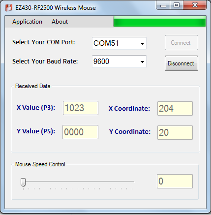
PROJECT DESCRIPTION A simple easy to use wireless mouse developed using TI EZ430-RF2500 RF Module. The project is rather simple. All you need is a resistive/capacitive touch screen (I got mine from a mobile repair shop) and the EZ430-RF2500 kit and you are ready to go. I use a coin cell battery (3V) to power the touch screen and EZ430 Target module. The X axis and Y axis data is obtained from the touch screen via A/D conversion using the EZ430-RF2500 module. The data is then transferred to the other target board connected to the Laptop/PC (via a Serial UART interface). The data obtained is then processed via a application GUI which i developed in Visual C# programming language using Visual Studio 2010. The GUI interacts with the windows and generates mouse actions accordingly. The application simulates all mouse actions including the mouse scroll. I have attached the source code for the Application GUI along with the other download files since you will need to edit certain conditions in the mouse logic code in case you want to make one by yourself. Use Visual Studio 2010 or higher to edit the code.
Fig: Application GUI for the Project
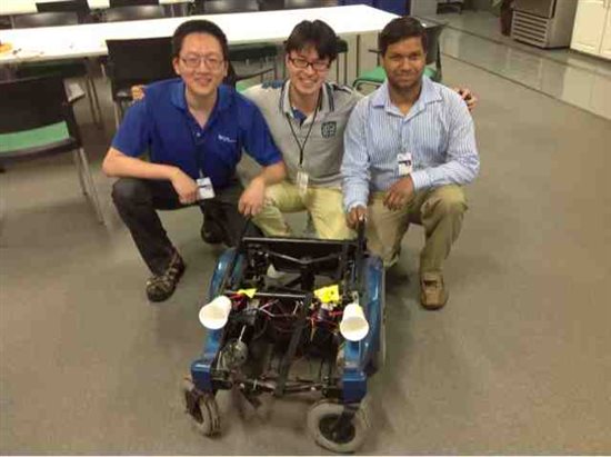
Fig: Wireless Mouse (Just a Resistive Touch Screen, a EZ430-RF2500 Target module, some LEDs and a coin cell battery to power the unit) |
[View:http://www.youtube.com/watch?v=L04wjp8Pzxg] |
USER'S GUIDE: You will need to upload the codes to both the EZ430-RF2500 Target Modules for working with the GUI. The code for the target modules and the GUI Source Code can be downloaded from the link below: [View:http://e2e.ti.com/cfs-file.ashx/__key/communityserver-components-userfiles/00-00-09-14-89-Attached+Files/5008.ez430_2D00_rf2500-wireless-mouse-project.rar] I have tried my best to comment the code properly for those who are new to the MSP430 development environment. You can also view the video for the demonstration of the GUI. The link is embedded in this post. To upload the code to EZ430 Module, you can either use CCS (Code Composer Studio) or IAR Workbench. I personally prefer IAR Workbench just for this particular module since it's easier to work with the header files in IAR Workbench. You will need to use SimpliciTI Library files for working with the code that i have used. You can download it from here: http://www.ti.com/tool/simpliciti (Download the version for MSP430). Note: The X-axis and Y-axis data are read via the P3 and P5 pins on the Target module respectively. For any queries and suggestions, feel free to drop me a mail. |

PROJECT DESCRIPTION We are developing a direct email notification system to Product/Test engineers within TI for when there is a problem with their Castle Handler on the test floor. Our MSP430 Launchpad "listens" to the communication between the Tester and Handler and continuously checks for jam codes that can occur during testing. When one of these jam codes come up, our MSP430 writes a file to a laptop and sends an email to the engineer that there has been a problem on the test floor. This project solves the wasted time that a Product/Test engineer might believe their tests are running but when, in reality, the Handler is stuck waiting for someone to clear the jam code. We hope that with more time and testing on our design, we could possibly create an attachment that could clear the most common error codes that occur during testing and also notify the engineer without a laptop connected. In the end, this will benefit both the engineers and the company as it decreases wasted time and therefore increases savings for the company. TEAM MEMBERS:
PROJECT FEATURES:
| Youtube Video: To be added |
RESOURCES: To be added |
USER'S GUIDE: To be added |
PROJECT DESCRIPTION Do you have the experience that you cannot connect to a wireless AP in a crowded place? Since the number of wireless devices keep increasing each year, the wireless congestion problem has become significant. In order to mitigate wireless traffic, visible light communication (VLC) is a promising RF-alternative. VLC transmit information using light, which is safe, efficient and secured. VLC also has advantages on the places where RF is not available, for example, hospital or aircraft. We design EP-Light BoosterPad- a simple visible light communication (VLC) transceiver working on MSP430 Launchpad. We demonstrate that we can achieve 32 Kbps using EP-Light. EP-Light shows the concept of future indoor lighting infrastructure, which not only lights up the room but also transmits information. EP-Light System Architecture: EP-Light composed of two major subsystems - transmitter and receiver. In the transmitter subsystem, MSP430 controls LED driver which provides high current and toggles the LED to transmit information. As for receiver subsystem, receiver contains a photodiode (PD) which converts light into current and a transimpedance amplifier (TIA) converts current into voltage. Additional analog signal conditioning circuit and digital interface are necessary for MSP430 to decode signal. EP-Light BoosterPack Gallery: Demo: In the demo setup, two computers are separated. Each computer connects to a MSP430 Launchpad with an EP-Light. One for transmitter and the other is receiver. Both computers listen to UART of MSP430. Keyboard input on transmitter will show up in the receiver's computer. [View:http://www.youtube.com/watch?feature=player_embedded&v=efpZW0v3jrU] TEAM MEMBERS:
PROJECT FEATURES:
|
RESOURCES: Using the "Insert File" button above, upload all of your code, design files, schematics, documentation, bill of materials (BOM), etc. I suggest you zip your content together and upload it as one large file. |
USER'S GUIDE: Use this section to explain how someone can use your project. Feel free to include your "how-to-guide" directly on this webpage, or include it as an embedded file (word document, PDF, etc) using the "Insert File" button above. |
Demo Video: [View:http://www.youtube.com/watch?v=5-tPJojaGgI&feature=youtu.be]
RESOURCES: [View:http://e2e.ti.com/cfs-file.ashx/__key/communityserver-components-userfiles/00-00-15-36-44-Attached+Files/6403.code-and-schematic.zip]
| ||
|
PROJECT DESCRIPTION A microcontroller based PC display Oscilloscope. TEAM MEMBERS: Ashwin Ashok PROJECT FEATURES:
|
PROJECT DESCRIPTION The ideabehindtheprojectwas bornfrom thefollowingproblemconcerning the useof anandroid tabletascarputer.One of the limitationsof using atablet ascarputeris the absenceofFM radioin almostall tabletsout there. The launchpad, in this caseis used to controlvia theI2C protocol,thevery cheapPhilipsTEA5767radio module (1.9$ on ebay).The communication between theandroid appandthe launchpadis througha cheapbluetooth module(HC-5)using the UART protocolof the MSP430G25. TEAM MEMBERS:
PROJECT FEATURES:
| [View:http://www.youtube.com/watch?v=v1GQ98AB56E&feature=player_embedded] |
RESOURCES: |
USER'S GUIDE: |
USER'S GUIDEYou need to upload a code to the MSP430g2553 microcontroller for working with the GUI. The code and the application GUI can be downloaded from the link below: [View:http://e2e.ti.com/cfs-file.ashx/__key/communityserver-components-userfiles/00-00-09-14-89-Attached+Files/6761.msp430-controlware.rar] Extract the contents of the download file and load the MSP430_ControlWare project in Code Composer Studio and upload the code to the MSP430 Launchpad (MSP430g2553 uC). You can also view the video for the demonstration of the GUI. The link is embedded in this post. How to Upload Code to the MSP430 Launchpad? Open CCS and Click on the Projects Option at the Top and Select the Import Existing CCS Eclipse Project option. Enter the directory location where you have extracted the download files and Click Finish. Select the Project in the Project Explorer and Click on the Debug Option. Note: Incase you find that the GUI is not working, please install .NET Framework 4.0 from here: LINK For any queries and suggestions, feel free to drop me a mail. |
Simple rear bike light on MSP430 The device increases safety of trips to a night-time, based on MSP430F2011. Contains a minimum of details.   As a radiator of light three red light-emitting diodes (LED) with a diameter of 10 mm are used. Current of a LED doesn't exceed 7 мА at completely charged batteries. As the power supply are used 4хААА by NiMH of 2100 mah. The device has three operating modes: - waiting mode (stand by) - mode 1/3 (cyclic blinking of one LED) - mode 3/3 (cyclic blinking of three LEDs) Frequency of a blinking of LEDs of 1 Hz. 700 ms off, 300 ms on. In a waiting mode the microcontroller is in the LP4 mode. In a mode 3/3 in LP3. Power switch not exist. |
RESOURCES: Electric circuit of the device (eagle): https://drive.google.com/file/d/0B6EjwYCeu3pcQzBQczg1cXBJYTA/edit?usp=sharing Firmware files (Code Composer ver.: 5.5.0.00077 ): https://drive.google.com/file/d/0B6EjwYCeu3pcbGI0ZXlPZG52ZDg/edit?usp=sharing |
| Expermnetal Board for MSP430 and TIVA Launchpads PROJECT FEATURES: Strictly speaking this is not a project but I thought this will help you to build great projects based on MSP430, TIVA and other launch pads. This is basically an experiment board designed to fit on various Launchpads from TI. Have a look at the following pics for your information. As you can see, these boards are Double sided PTH boards with matching Red solder masking color. These boards are from Iknowvations. You can buy these boards from Iknowvations Shoppee. The board cost only 4.95 US $ | [View:http://www.youtube.com/watch?v=4p_vHeHqvQo] |
RESOURCES:
|
USER'S GUIDE: Use these boards as per your project needs. |
PROJECT DESCRIPTION This project presents a programming of MSP430G2553 to control buck converter for charging a battery 12V9Ahr. In this work the design of the buck converter is not performed. TEAM MEMBERS:
PROJECT FEATURES:
| The figure 1 shows the structure of the buck converter. The transistor SW is controlled by the PWM signal pin P1.2. For controlling the battery charging, the current iL and voltage Vb are read by ADC. The figure 2 shows the waveform of current iL. To read the current iB, which is average value of iL, the ADC is triggered in middle time which the transistor is off. To do this, the ADC is triggered by TACCR2, TACCR1 is signal of PWM to transistor SW. Figure 3 shows the signal PWM and trigger ADC. Figure 1
Figure 2
Figure 3
Figure 4 shows the flowchart of the algorithm four steps, the step slow charging is not performed in the project. Compensator gains are not adjusted, because it must be taken into account the values of L and C. In this moment, the converter wasn't builded. Figure 4
|
PROJECT DESCRIPTION This project presents a simple implementation of algorithm P&O to tracker the maximum power point (MPPT) of a solar panel. For the power circuit, was used the buck converter. TEAM MEMBERS:
PROJECT FEATURES:
| The algorithm P&O, is show in Figure 1 and the circuit in Figure 2. I suggest using a rail-to-rail amplifier with 3.3V supply for best result and protection of the ADC. The OPA2350 of TI is a good choice. The tracking of the maximum power point is done every 0.5 seconds.
|
PROJECT DESCRIPTION To help you add NFC to your LaunchPad projects quickly! The following instruction sets were developed to provide users with a detailed set of instructions to get NFC running on their LaunchPad and to show them the available features using the new TRF7970ABP designed by DLP Design. Two instruction sets were created: one for the G2553 LaunchPad and one for the 5529 LaunchPad. For the G2553 LaunchPad we will show you how to visually (by LED) see what type of tag is being presented to the LaunchPad and via a serial monitor program such as PuTTY or HyperTerminal you can read out tag types, UID, RSSI and the # of tags. For the 5529 LaunchPad we will show you how to use our NFCLink software and a GUI provided by Stollman to read tags, write tags, run the NFC transceiver in Peer-to-Peer mode using two BoosterPacks or an NFC device and place the transceiver in card emulation mode.
PROJECT FEATURES: For 2553 (link to instructions under image):
For 5529 (link to instructions under image):
|
For the G2553 LaunchPad: http://www.ti.com/lit/pdf/slab068 For the 5529 LaunchPad: http://www.ti.com/lit/pdf/slab069 |
PROJECT DESCRIPTION The scope of this project is to provide users with a set of instructions to get WiFi running on the G2553 LaunchPad using the new CC3000 BoosterPack. The instructions will walk the user through flashing the MSP430 and how to send UDP packets from the LaunchPad. PROJECT FEATURES:
|
Instruction Set: http://www.ti.com/lit/pdf/slab067 |
PROJECT DESCRIPTION This tutorial shows how to interface the ePaper BoosterPack from Pervasive Displays with the MSP-EXP430G2 LaunchPad. This BoosterPack is bundled with either a 1.44", 2" and 2.7" ePaper display and is available @ http://www.pervasivedisplays.com/kits/ext_kit This example uses Code Composer Studio to program the MSP-EXP430G2 LaunchPad. Once programmed, we can communicate and control the LaunchPad to display various images, shapes, text, etc on the ePaper display through serial UART commands with the help of a Graphical User Interface (GUI). PROJECT FEATURES:
| [View:http://www.youtube.com/watch?v=d2Kj2NwmzB0] |
RESOURCES: Here is a zip file that includes the CCS project example, installer for the EPD GUI tool as well as some sample images. A power point is also packaged with some instructions. [View:http://e2e.ti.com/cfs-file.ashx/__key/communityserver-components-userfiles/00-00-01-39-39-Attached+Files/7522.epaper_5F00_boosterpack.zip] |
|
PROJECT DESCRIPTION This tutorial shows how to monitor a 3-axis analog accelerometer wirelessly using the MSP-EXP430F55209LP LaunchPad & CC110L SubGHz RF BoosterPack. This example uses Energia to program this complete solution. One LaunchPad will continuously read accelerometer data and will send out a wireless transmission whenever the total acceleration exerted on the accelerometer is greater than a pre-defined threshold. Once threshold is exceeded "ALARM!" is sent wirelessly to another LaunchPad, which will toggle an LED on and off when the "ALARM" packet is received. PROJECT FEATURES:
| [View:http://www.youtube.com/watch?v=pQ0IbEemEJY] |
RESOURCES: This uses a code example that comes pre-loaded in Energia v10 and later, but is slightly modified. Accelerometer + Transmitter code: /** // The AIR430BoostFCC library uses the SPI library internally. Energia does not // ----------------------------------------------------------------------------- // Data to write to radio TX FIFO (60 bytes MAX.) // Data to read from radio RX FIFO (60 bytes MAX.) // ----------------------------------------------------------------------------- void printTxData() void printRxData() // ----------------------------------------------------------------------------- void setup() // Setup serial for debug printing. void loop() int result = sqrt(x_axis*x_axis + y_axis*y_axis + z_axis*z_axis)*100/82; Serial.print(x_axis); Monitor code /** // The AIR430BoostFCC library uses the SPI library internally. Energia does not // ----------------------------------------------------------------------------- // Data to write to radio TX FIFO (60 bytes MAX.) // Data to read from radio RX FIFO (60 bytes MAX.) // ----------------------------------------------------------------------------- void printTxData() void printRxData() // ----------------------------------------------------------------------------- void setup() // Setup serial for debug printing. void loop() // // Turn on the receiver and listen for incoming data. Timeout after 1 seconds. |
Helpful Links: www.ti.com/launchpad www.ti.com/tool/430boost-cc110l www.ti.com/tool/msp-exp430f5529lp www.energia.nu |
PROJECT DESCRIPTION This project presents the control of a stepper motor with msp430 launch pad. The timer is used to control the speed of step , this way , microcontroller is free to do other activities, the program allows you to control speed, type of stepper, direction of rotation and on/off the motor. TEAM MEMBERS:
PROJECT FEATURES:
| [View:http://www.youtube.com/watch?v=qH18N7DufbQ] The pin P2.0 to coil A, P2.1 to coil B, P2.2 to coil A' and P2.3 to coil B' . In the source code, 'ligar' is to turn on (0x0F) or off (0x00) the motor, 'tipo_passo' select the type of stepper 0->full stepper, 1->half stepper and 2->full stepper with 2 coil, 'index_passo' control de current stepper, 'direcao' control the direction of rotation, 'tempo' control the speed and 'n_passo' is a count of stepper. |